ESP32 Smart Car Development Documentation
Table of Contents
- Project Overview
- Hardware Configuration
- Communication Architecture
- CAN Communication Protocol
- ESP32 Code Description
- Debugging and Maintenance
1. Project Overview
1.1 Project Introduction
This project implements a 4-wheel smart car based on the ESP32-S3, communicating with the host computer (ROS2) via CAN bus, and supporting Bluetooth gamepad control.
1.2 Features
| Feature | Description |
|---|---|
| Motor control | 4 encoder motors, PWM speed control |
| Motion mode | differential steering mode |
| Communication method | CAN bus TWAI (primary), Bluetooth gamepad (local) |
| Sensors | MPU6050 gyroscope, QMC5883L magnetometer (optional), encoders |
| Reported data | battery voltage, attitude angle, linear velocity, angular velocity, motor speed, encoder cumulative value |
1.3 Development Guide
Development board documentation
This project uses the VS Code + PlatformIO development environment.
If you have not used it before, you can search for related tutorials on Bilibili; it is easy to get started.
2. Hardware Configuration
2.1 Hardware List
| Device | Model/Specification | Quantity | Description |
|---|---|---|---|
| Main control | ESP32-S3-DevKitC-1 | 1 | main controller, integrated motor driver |
| Motor | 36-555 | 4 | DC geared motor |
| Encoder | Hall encoder | 4 | integrated on the motor |
| Gyroscope | MPU6050 | 1 | built into the development board |
| Magnetometer | QMC5883L | 1 | not used |
| Bluetooth gamepad | BLE gamepad | 1 | local control |
| CAN transceiver | USB-to-CAN analyzer | 1 | connected to the computer |
| CAN-to-TTL module | CAN-to-TTL | 1 | connected to the ESP32 |
2.2 Pin Assignment
ESP32-S3 引脚资源:
├── GPIO5        : TWAI TX (CAN发送)
├── GPIO6        : TWAI RX (CAN接收)
├── GPIO2        : ADC (电池电压检测)
├── GPIO46       : LED指示
└── 编码器引脚   : 通过配置读取
2.3 CAN Bus Wiring
ESP32-S3              CAN转TTL模块
─────────────────     ────────────────
GPIO5 (TX)       →      TX
GPIO6 (RX)       →      RX
3.3V             →      VCC
GND              →      GND

CAN转TTL模块另一头       CAN收发器              电脑
──────────────────     ──────────────      ───────────
CANH              →      CANH       ->         usb
CANL              →      CANL
2.4 CAN Transceiver and Host Computer
Please see the folder "CAN Transceiver Documentation" in the delivery directory.
3. Communication Architecture
┌─────────────┐     USB-CAN      ┌──────────────┐    CAN总线    ┌─────────────────┐
│   ROS2 PC   │ ←──────────────→ │ USB-CAN收发器 │ ←───────────→ │ CAN转TTL模块   │
└─────────────┘                  └──────────────┘               └───────┬─────────┘
                                                                        │
                                                                        ↓
┌─────────────┐                          ┌────────────────────────────────────┐
│ 蓝牙手柄     │ ←──── BLE ──────────────→ │          ESP32-S3 (TWAI)          │
│ (本地控制)   │                          │  ┌────────────────────────────────┐│
└─────────────┘                          │  │ •  TWAI控制器(硬件处理CAN协议) ││
                                          │  │ •  蓝牙优先级最高               ││
                                          │  └────────────────────────────────┘│
                                          └───────────────────────────────────┘
4. CAN Communication Protocol
4.1 Communication Parameters
| Parameter | Value |
|---|---|
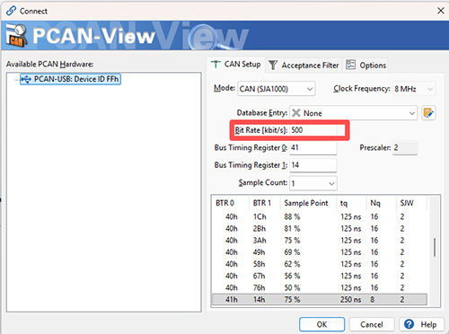
| Baud rate | 500Kbps |
| Frame format | standard frame (11-bit ID) |
| Data format | little-endian (low byte first) |
| Filter | receive all frames |
4.2 CAN ID Allocation Table
| ID | Direction | Function | Data length |
|---|---|---|---|
| 0x101 | uplink | attitude data | 8 bytes |
| 0x102 | uplink | motor speed (4 motors) | 8 bytes |
| 0x103 | uplink | encoder cumulative value (1-2) | 8 bytes |
| 0x104 | uplink | encoder cumulative value (3-4) | 8 bytes |
| 0x105 | uplink | sync frame (packet loss detection + latency estimation) | 8 bytes |
| 0x201 | downlink | PWM mode control (+seq) | 8 bytes |
| 0x202 | downlink | ROS speed mode control (+seq) | 8 bytes |
| 0x203 | downlink | brake command (+seq) | 2 bytes |
4.3 Uplink Data Frame Format (ESP32 → Host)
0x101 - Attitude Data (8 bytes)
| Byte | Type | Name | Unit | Description |
|---|---|---|---|---|
| 0-1 | uint16 | voltage | 0.01V | battery voltage, e.g. 241=24.1V |
| 2-3 | int16 | angleZ | deg | heading angle, -180~180 |
| 4-5 | int16 | linearX | mm/s | X-axis linear velocity |
| 6-7 | int16 | linearY | mm/s | Y-axis linear velocity |
Test examples:
| Scenario | Data (hex) | Description |
|---|---|---|
| stationary | F1 00 00 00 00 00 00 00 |
voltage 24.1V, heading 0°, linear velocity 0 |
| turning right 90° | F1 00 5A 00 00 00 00 00 |
voltage 24.1V, heading 90°, linear velocity 0 |
| moving forward | F1 00 00 00 64 00 00 00 |
voltage 24.1V, heading 0°, X linear velocity 100mm/s |
| fully charged moving forward | C8 00 00 00 64 00 00 00 |
voltage 20.0V, heading 0°, X linear velocity 100mm/s |
0x102 - Motor Speed (8 bytes)
| Byte | Type | Name | Unit |
|---|---|---|---|
| 0-1 | int16 | rpm1 | RPM |
| 2-3 | int16 | rpm2 | RPM |
| 4-5 | int16 | rpm3 | RPM |
| 6-7 | int16 | rpm4 | RPM |
Test examples:
| Scenario | Data (hex) | Description |
|---|---|---|
| stationary | 00 00 00 00 00 00 00 00 |
all stopped |
| forward | 32 00 1E 00 0A 00 14 00 |
Motor 1=50, Motor 2=30, Motor 3=10, Motor 4=20 RPM |
| backward | CE FF E2 FF F6 FF 0A 00 |
Motor 1=-50, Motor 2=-30, Motor 3=-10, Motor 4=10 RPM |
0x103 - Encoder Cumulative Value 1-2 (8 bytes)
| Byte | Type | Name | Description |
|---|---|---|---|
| 0-3 | int32 | encoder1 | cumulative pulse count of encoder 1 |
| 4-7 | int32 | encoder2 | cumulative pulse count of encoder 2 |
Test example: [0x64 0x00 0x00 0x00 0xE8 0x03 0x00 0x00] → Encoder 1=100, Encoder 2=1000
0x104 - Encoder Cumulative Value 3-4 (8 bytes)
| Byte | Type | Name | Description |
|---|---|---|---|
| 0-3 | int32 | encoder3 | cumulative pulse count of encoder 3 |
| 4-7 | int32 | encoder4 | cumulative pulse count of encoder 4 |
Test example: [0x00 0x00 0x00 0x00 0x10 0x27 0x00 0x00] → Encoder 3=0, Encoder 4=10000
0x105 - Sync Frame (8 bytes, ESP32 → PC, 1Hz)
Used by the host computer to implement packet loss detection and latency estimation. Sent periodically by the ESP32, carrying system uptime and frame sequence number.
| Byte | Type | Name | Description |
|---|---|---|---|
| 0-3 | uint32 | uptime_ms | system uptime (ms), can be used for latency estimation |
| 4-5 | uint16 | frame_seq | global frame sequence number, monotonically increasing; a jump indicates packet loss |
| 6 | uint8 | rx_seq_echo | sequence number of the most recently received downlink frame; the host can calculate RTT from it |
| 7 | uint8 | reserved | reserved |
Test examples:
| Scenario | Data (hex) | Description |
|---|---|---|
| 1 second after startup | E8 03 00 00 05 00 00 00 |
uptime=1000ms, seq=5, rx_echo=0 |
| running for 10 seconds | 10 27 00 00 32 00 0A 00 |
uptime=10000ms, seq=50, rx_echo=10 |
4.4 Downlink Data Frame Format (Host → ESP32)
0x201 - PWM Mode Control (8 bytes)
| Byte | Type | Name | Range | Description |
|---|---|---|---|---|
| 0-1 | int16 | x_speed | -100~100 | X-axis power percentage |
| 2-3 | int16 | y_speed | -100~100 | Y-axis power percentage |
| 4-5 | int16 | z_speed | -100~100 | Z-axis power percentage |
| 6 | uint8 | seq | 0~255 | frame sequence number, incremented by the host, used for packet loss detection |
| 7 | uint8 | reserved | - | reserved |
Test examples (host fills: CAN ID = 0x201, data 8-byte hex, data length 8):
| Scenario | Data (hex 8 bytes) | X | Z | Description |
|---|---|---|---|---|
| forward 50% | 32 00 00 00 00 00 00 00 |
50 | 0 | X-axis 50% forward |
| forward 100% | 64 00 00 00 00 00 00 00 |
100 | 0 | X-axis full speed forward |
| backward 50% | CE FF 00 00 00 00 00 00 |
-50 | 0 | X-axis -50% backward |
| clockwise rotation 50% | 00 00 00 00 32 00 00 00 |
0 | 50 | Z-axis 50% right turn |
| counterclockwise rotation 50% | 00 00 00 00 CE FF 00 00 00 |
0 | -50 | Z-axis -50% left turn |
| stop | 00 00 00 00 00 00 00 00 |
0 | 0 | all zero |
Note: rubber wheels do not support lateral movement; fill 0 for the Y axis.
0x202 - ROS Speed Mode Control (8 bytes)
| Byte | Type | Name | Unit | Description |
|---|---|---|---|---|
| 0-1 | int16 | x_speed | mm/s | X-axis linear velocity |
| 2-3 | int16 | y_speed | mm/s | Y-axis linear velocity |
| 4-5 | int16 | z_speed | deg/s | Z-axis angular velocity |
| 6 | uint8 | seq | 0~255 | frame sequence number, incremented by the host, used for packet loss detection |
| 7 | uint8 | reserved | - | reserved |
Test examples (host fills: CAN ID = 0x202, data 8-byte hex, data length 8):
| Scenario | Data (hex 8 bytes) | X(mm/s) | Z(deg/s) | Description |
|---|---|---|---|---|
| forward 0.2m/s | C8 00 00 00 00 00 00 00 |
200 | 0 | about 0.2m/s forward |
| forward 0.8m/s | 20 03 00 00 00 00 00 00 |
800 | 0 | about 0.8m/s forward |
| backward 0.2m/s | 38 FF 00 00 00 00 00 00 |
-200 | 0 | about 0.2m/s backward |
| rotation 90°/s | 00 00 00 00 5A 00 00 00 |
0 | 90 | 90°/s clockwise rotation |
| stop | 00 00 00 00 00 00 00 00 |
0 | 0 | all zero |
0x203 - Brake Command (2 bytes)
| Byte | Type | Name | Range | Description |
|---|---|---|---|---|
| 0 | uint8 | brakeForce | 0~100 | brake force, 0=coast to stop, 1~100=active braking + parking hold |
| 1 | uint8 | seq | 0~255 | frame sequence number, incremented by the host, used for packet loss detection |
- brakeForce = 0: coast to stop (motor released, freely decelerates to a stop)
- brakeForce > 0: active braking → motor short-circuit braking until fully stopped → automatically enters parking position hold (encoder closed-loop back-calc, resists external pushing force)
Test examples (host fills: CAN ID = 0x203, data length 2):
| Scenario | Data (hex) | Description |
|---|---|---|
| coast to stop | 00 |
brake force 0, release the motor to stop freely |
| gentle braking | 30 |
30% brake force braking, parking hold after stopping |
| emergency braking | 64 |
100% full-force braking, parking hold after stopping |
5. ESP32 Code Description
5.1 Code Structure
cust20/
├── src/
│   ├── main.cpp          # 主程序入口
│   └── main.h            # 全局变量和函数声明
├── lib/
│   ├── CanBus/           # CAN通信模块
│   │   ├── CanBus.h/cpp      # MCP2515方案(参考)
│   │   ├── CanBusTTL.h/cpp   # CAN转TTL方案(参考)
│   │   └── CanBusTWAI.h/cpp  # TWAI方案(当前使用)
│   ├── Config/            # 配置存储
│   ├── ControlStick/      # 蓝牙手柄
│   ├── encoder/           # 编码器驱动
│   ├── motor/            # 电机驱动
│   ├── Pid/              # PID控制
│   ├── protocal/         # 通信协议定义
│   └── Head.h            # 硬件参数配置
└── platformio.ini        # 项目配置
5.2 Core Class Description
CanBusTWAI Class
Uses the built-in TWAI controller of the ESP32-S3 to automatically process the CAN protocol via hardware.
class CanBusTWAI
{
public:
    // 初始化TWAI控制器
    bool begin(CanRxCallback callback);

    // 发送原始CAN帧
    bool sendFrame(uint16_t canId, const uint8_t* data, uint8_t len);

    // 发送姿态数据帧
    bool sendPoseData(float voltage, int16_t angleZ, ...);

    // 发送电机转速帧
    bool sendMotorRpm(int16_t rpm1, int16_t rpm2, int16_t rpm3);

    // 发送编码器累计值帧
    bool sendEncoderTicks(int32_t tick1, int32_t tick2, ...);
};
handleCanFrame Callback Function
Parses the CAN commands sent by the host:
0x201PWM mode → callscontrolEMotors()0x202ROS mode → callscontrolEMotors()after unit conversion0x203brake command → callsstop()
5.3 Multi-task Architecture
The ESP32-S3 dual-core processor assigns tasks as follows:
| Task | Core | Description |
|---|---|---|
loop() |
Core 1 | main loop |
xCore_task |
Core 0 | motor control, sensor acquisition |
twaiTask |
Core 0 | CAN frame reception (independent task) |
5.4 Key Parameters (must be adjusted yourself)
/**Head.h*/
// 根据实际情况修改参数配置
const int maxRpm = 110;              // 电机最大转速RPM
const int gear = 90;                 // 减速比
const float wheelCircumference = PI * 80;  // 轮子周长(mm)
const int wheelSpacing = 220;        // 轮间距(mm)
const int wheelBase = 200;           // 轴距(mm)
/**main.h*/
// 可以根据实际情况修改参数配置
const int gapNotice = 100;  // 定时发送状态的间隔,单位毫秒
const int outPutCountLimit = 10; // 电机满负荷运行多少次后降低速度
const float maxDe = 0.3;    // 电机如果超负荷运行,最大降速比例
/**pid.h*/
// 必须根据实际情况修改参数配置,例如下行数据的频率,影响到电机的转速
double kp = 0.25;  // 比例系数
double ki = 0.02;  // 积分系数
double kd = 0.5;  // 微分系数
5.5 Data Reporting Period
- Attitude data: 100ms (10Hz)
- Motor speed: 100ms (10Hz)
- Encoder: 100ms (10Hz)
6. Debugging and Maintenance
6.1 Debugging Methods
Serial Monitor
Baud rate 115200, can view:
-
TWAI initialization status
-
Received commands
-
Motor speed feedback
-
Error messages
6.2 Contact Information
If you have any questions, please contact technical support at 15827639032.
Appendix
A. CAN Frame Test Quick Reference Table
Downlink Test (PC host → ESP32, sent via USB-CAN analyzer)
| Operation | CAN ID | Data (hex 8 bytes) | Data length |
|---|---|---|---|
| 50% power forward | 0x201 | 32 00 00 00 00 00 01 00 |
8 |
| 100% power forward | 0x201 | 64 00 00 00 00 00 02 00 |
8 |
| 50% power backward | 0x201 | CE FF 00 00 00 00 03 00 |
8 |
| 50% clockwise rotation | 0x201 | 00 00 00 00 32 00 04 00 |
8 |
| 50% counterclockwise rotation | 0x201 | 00 00 00 00 CE FF 05 00 |
8 |
| stop | 0x201 | 00 00 00 00 00 00 06 00 |
8 |
| forward 0.2m/s | 0x202 | C8 00 00 00 00 00 01 00 |
8 |
| forward 0.8m/s | 0x202 | 20 03 00 00 00 00 02 00 |
8 |
| backward 0.2m/s | 0x202 | 38 FF 00 00 00 00 03 00 |
8 |
| rotation 90°/s | 0x202 | 00 00 00 00 5A 00 04 00 |
8 |
| stop | 0x202 | 00 00 00 00 00 00 05 00 |
8 |
| coast to stop | 0x203 | 00 01 00 00 00 00 00 00 |
2 |
| gentle braking + parking | 0x203 | 1E 02 00 00 00 00 00 00 |
2 |
| emergency braking + parking | 0x203 | 64 03 00 00 00 00 00 00 |
2 |
Uplink Test (ESP32 → PC host, received via USB-CAN analyzer)
| Data meaning | CAN ID | Data (hex 8 bytes) |
|---|---|---|
| voltage 24.1V, stationary | 0x101 | F1 00 00 00 00 00 00 00 |
| voltage 24.1V, heading 90° | 0x101 | F1 00 5A 00 00 00 00 00 |
| voltage 24.1V, X linear velocity 100mm/s | 0x101 | F1 00 00 00 64 00 00 00 |
| Motor 1=50, 2=30, 3=10, 4=20 RPM | 0x102 | 32 00 1E 00 0A 00 14 00 |
| Encoder 1=100, Encoder 2=1000 | 0x103 | 64 00 00 00 E8 03 00 00 |
| Encoder 3=0, Encoder 4=10000 | 0x104 | 00 00 00 00 10 27 00 00 |
| sync: uptime=1000ms, seq=5 | 0x105 | E8 03 00 00 05 00 00 00 |
USB-CAN Analyzer Host Computer Operation Steps
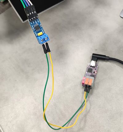
- Wire as shown below: connect the Dupont wires to esp2, and plug the USB into the computer.
-
Install the driver and host software according to the documentation in the materials package.
-
Upload the ESP32 code to the development board.
-
Open the host software; a "connect" dialog will pop up automatically. If not, connect manually.
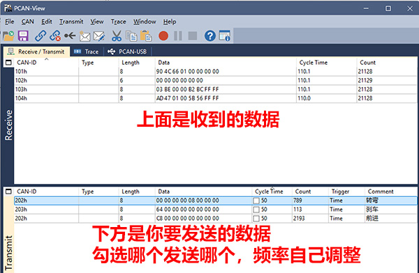
- Configure the test packet yourself.
B. Revision History
| Version | Date | Changes |
|---|---|---|
| 1.0 | 2026-05-12 | initial version |
| 1.1 | 2026-05-14 | switched to TWAI solution, added CAN transceiver wiring instructions |
| 1.2 | 2026-05-27 | added complete test data tables for each CAN ID and USB-CAN host software operation instructions |
| 1.3 | 2026-06-26 | added 0x105 sync frame; added seq sequence number to 0x201/0x202/0x203; expanded 0x102 to 4 motors 8 bytes |