UNO R3 PRO
1. Introduction
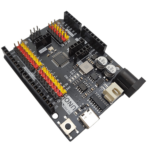
The Qiguopai UNO R3 PRO is a microcontroller board based on the ATmega328, fully compatible with the ARDUINO UNO REV3. It has 14 digital input/output pins (6 of which can be used as PWM outputs), 8 analog inputs, a 16 MHz quartz crystal, a USB Type-C connector, a power jack, a dedicated lithium battery connector, 1 ICSP header, and a reset button. It contains everything needed to support the microcontroller; simply connect it to a computer with a USB cable, or power it with an AC-DC adapter or a battery to get started.
Please note that the 1 ICSP header is used to write firmware to the ATMEGA328P-PU or to download programs, but usually both of these chips are already well programmed.
The UNO R3 PRO is the best board to start learning electronics and programming. If this is your first time trying out the platform, the UNO is the most ideal board for you.
2. Technical Specifications
| Parameter Name | Parameter |
|---|---|
| Microcontroller | ATmega328P-PU |
| Operating Voltage | 5V |
| Input Voltage (Recommended) | 7-12V (DC) |
| Digital Pins | 14 (6 of which provide PWM output) |
| PWM Digital I/O Pins | 6 (D3, D5, D6, D9, D10, D11) |
| Analog Input Pins | 8 (A0-A7) |
| DC Current per I/O Pin (S) | 20 mA (mAh) |
| 5V DC Power Output | 2500 mA (mAh) |
| Flash Memory | 32 KB (ATmega328), of which 0.5 KB is used by the bootloader |
| SRAM | 2 KB (ATmega328P-PU) |
| EEPROM | 1 KB (ATmega328P-PU) |
| Clock Frequency | 16 MHz |
| On-board LED | D13 |
3. Features
This is an enhanced Arduino UNO-compatible development board with powerful upgrades over the official board.
-
The board uses a Type-C connection interface for more convenient connection.
-
The integrated wide-voltage power supply module provides 5V/2.5A output to the board, meeting the power needs of connected sensors or actuators and making projects run more stably.
-
A new battery holder connector is added for direct connection to dedicated lithium batteries.
-
Integrated G, V, S connectors allow sensors, actuators, servos, and displays to be connected directly without an expansion board, making it more convenient and easier to use.
-
Additional A6 and A7 analog interfaces are broken out for more expandable functionality.
-
Three sets of dedicated module connectors allow direct one-wire connections for convenient and practical use.
4. Board Dimensions
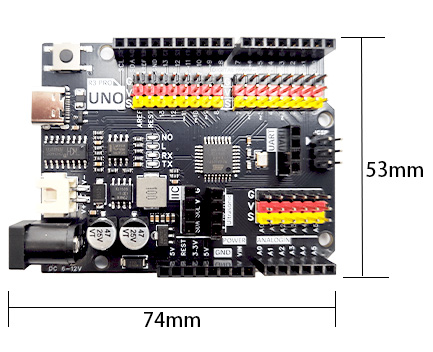
5. Board Anatomy
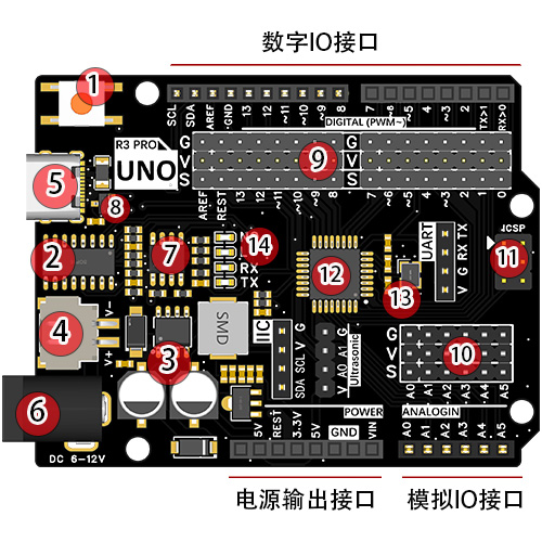
-
① Reset button
Press the reset button to re-run the program.
-
② USB serial chip
This chip is responsible for converting data received via USB into serial data for the main controller chip.
-
③ 5V/2A power supply module
The power supply module is responsible for powering the board. It regulates an external 6-12V power input to a 5V/2A/10W output, capable of driving multiple servos, toy motors, micro slides, and other devices.
-
④ 6-9V battery connector
A dedicated battery connector for AA battery holders or 18650 lithium battery holders, making the board easier to lay out when creating mobile projects.
-
⑤ USB connector
Responsible for program downloading and USB power supply.
-
⑥ 3.3V power chip
Provides 3.3V voltage output for the board.
-
⑦ External power and USB power automatic switchover controller
An automatic switchover control system composed of the FDN340P MOSFET and the LMV358IDGKR amplifier. By default the board is powered by the USB connector; when an external power source is connected, the controller automatically disconnects USB power and switches to the external supply, and when the external supply is removed it automatically switches back to USB. This function protects the computer from interference caused by the board's external power supply.
-
⑧ Self-recovering fuse
When a wrong connection on the board causes a short circuit, the fuse automatically disconnects the circuit between the board and the computer, protecting the computer's USB port from being burned out or the computer from freezing.
-
⑨ Digital G|V|S expansion connector
The on-board digital G|V|S connectors make connecting sensors or actuators more convenient and quick, and no expansion board is needed when building projects. G is the GND power negative terminal, V is the VCC power positive terminal, S is the IO signal interface, and G/V provides 5V/2A output power to meet the power requirements of most sensors and actuators.
-
⑩ Analog G|V|S expansion connector
The on-board analog G|V|S expansion connectors make connecting analog sensors more convenient and quick, and the newly added A6 and A7 analog input interfaces allow more sensors to be connected.
-
⑪ ICSP serial data interface
Connect to this interface when writing the initialization program to the board or downloading a program with a programmer.
-
⑫ ATMEGA328P main controller chip
The ATMEGA328P main controller chip is the brain of the board, responsible for program storage, execution, computation processing, signal input and output, and other functions.
-
⑬ Crystal oscillator
Provides the clock signal for the ATMEGA328P main controller chip.
-
⑭ LED indicator lights
The board has 4 LED indicators: (ON) is the power indicator that lights up when powered on; (RX)(TX) are serial signal indicators that blink during serial communication; (L) is the D13 pin LED that lights up when the D13 signal is High.
Note The Qiguopai UNO R3 PRO has resettable polyfuses that protect the computer's USB port from short circuits and overcurrent. If more than 500 mA of current is applied to the USB port, the fuse will automatically break the connection until the short circuit or overload is removed.
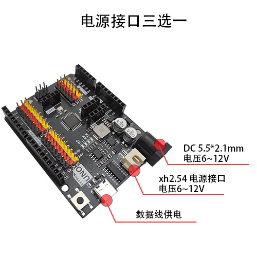
6. Dedicated Lithium Battery Connector
A dedicated battery connector for 14500 lithium batteries or 18650 lithium batteries, making layout easier when creating mobile projects.
7. Sensor and Expansion Accessory Connectors
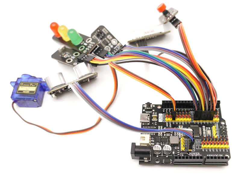
The on-board digital G|V|S connectors make connecting sensors or actuators more convenient and quick, and no expansion board is needed when building projects. G/V provides 5V/2.5A output power to meet the power requirements of most sensors and actuators.
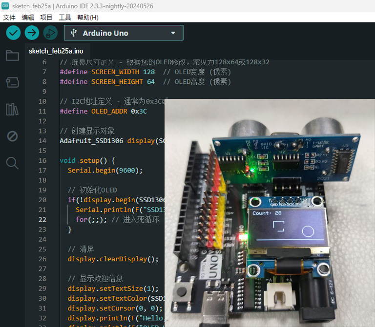
8. Ultrasonic Sensor Example
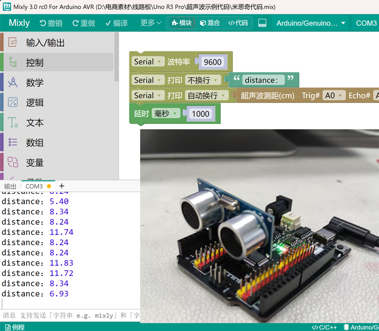
The board integrates two I2C interfaces, so the ultrasonic sensor can be plugged in directly or connected through jumper wires.
9. OLED Display Example
The board integrates two I2C interfaces, so the ultrasonic sensor can be plugged in directly or connected through jumper wires.