Overview
This is a solution for developing smart cars based on the Esp32 platform.
The development board has a built-in Esp32-S3 module with a 32-bit LX7 dual-core processor, supports a 240 MHz clock frequency, integrates Wi-Fi & BLE, uses an ipex RF coaxial antenna, and integrates 16MB FLASH and an audio codec, meeting users' requirements for low power consumption and high performance.
The motor driver is powerful enough to drive 4 DC motors or 2 stepper motors, and additionally provides 4 channels of full-speed PWM control, which can control 4 servos. It supports the PS2 Bluetooth gamepad, fully leveraging the powerful features of the PS2 gamepad.
The development board provides rich interface configurations, integrating 4 encoder motor interfaces, an OLED display interface, an IMU gyroscope interface, and a voltage detection module, without affecting other I2C devices.
Interface Parameters
** 12V Development Board **
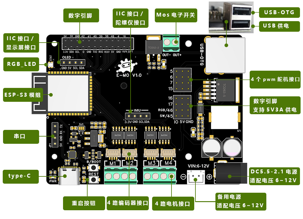
EMO_Lite Schematic: Click to download
Parameter description:
- ESP32-S3-WROOM-1-N8R8 module: 32-bit LX7 processor, 240 MHz main frequency, 8MB Flash, built-in Bluetooth and Wi-Fi dual modules;
- Uses high-performance driver chips, capable of driving 4 DC motors or 2 stepper motors;
- Additionally provides 4 channels of PWM output, capable of controlling 8 servos;
- Provides 2.2A (3.6A peak) output per channel, can run 4.5-13.5V DC motors;
- Supports Bluetooth gamepad remote control and provides MQTT IoT remote control;
- Rich interfaces: integrates two I2C interfaces, four encoder interfaces, and a Type-C interface, etc.;
- Recommended input voltage 6~12V, maximum current 3A.
** 24V Development Board **
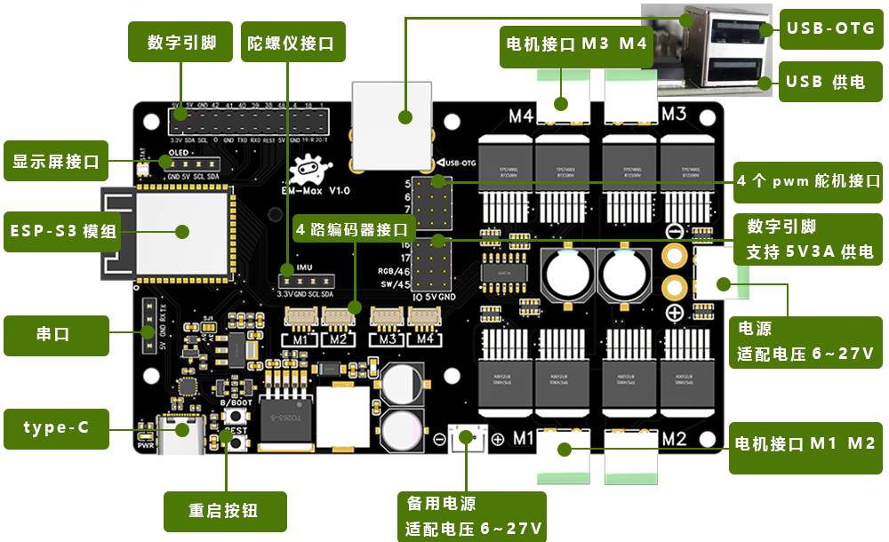
EM_MAX Schematic: Click to download
High-power development board differences:
Recommended voltage within 24V, limit test voltage 27V; Stable output current 30A; Under-voltage and over-voltage protection, thermal protection, short-circuit protection.
Power Supply Instructions
Power supply scheme:
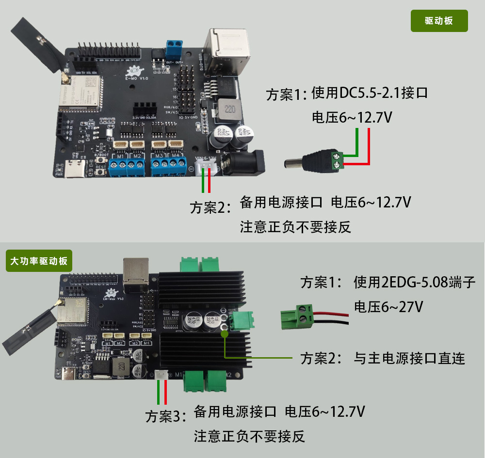 Power supply selection
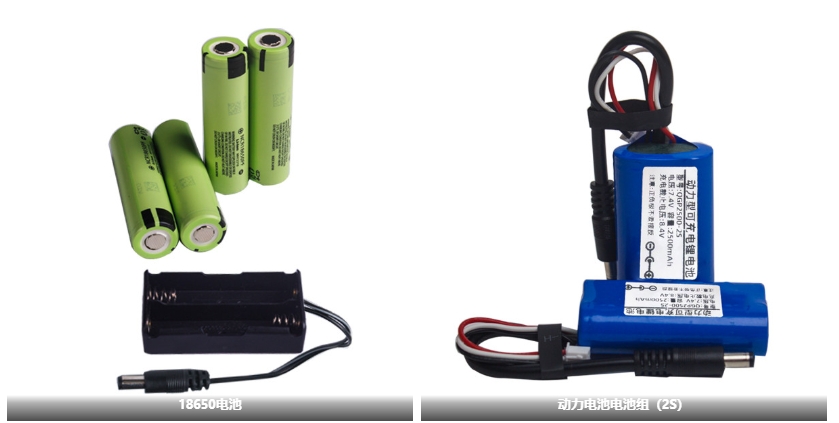
The main power supply of the motor driver is suitable for 6-12V, and needs to match the connected motor. Power supply selection is very important; insufficient power supply will make the system work unstably. It is recommended to use a power-type battery. Power batteries have a larger discharge current and stronger instantaneous output power.
Motor Wiring Instructions
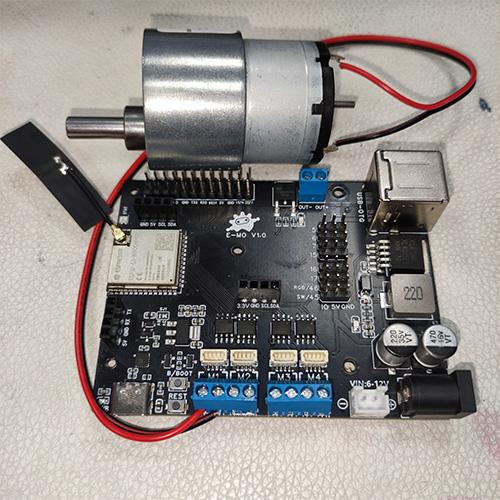
Brushed DC Motor
- Insert the power wire into the blue motor interface; polarity does not matter. If the motor rotates in the wrong direction, swap the positive and negative wire order of the motor.
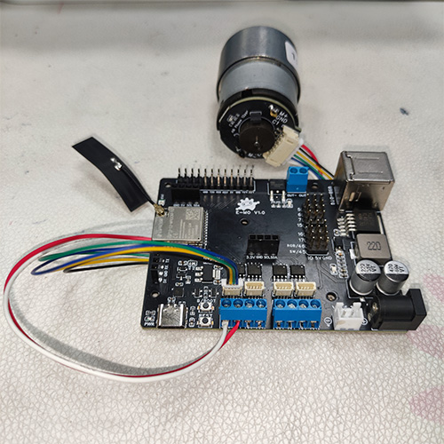
Encoder Motor
-
Insert the power wire into the blue motor interface; polarity does not matter. If the motor rotates in the wrong direction, swap the positive and negative wire order of the motor.
-
Insert the encoder data cable into the corresponding white interface.
Third-party Encoder Motor
- If using a third-party encoder, pay special attention to the wiring: there are pin labels on the back of the board, where VCC connects to the positive terminal and GND to the negative terminal. If connected incorrectly, it will short circuit and burn out the components;
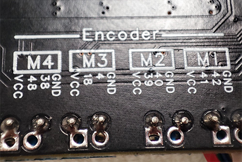
If using encoders, each encoder occupies 2 pins of the development board, so after using encoders, the corresponding 8 pins on the front of the development board will be occupied.
Servo Wiring Instructions
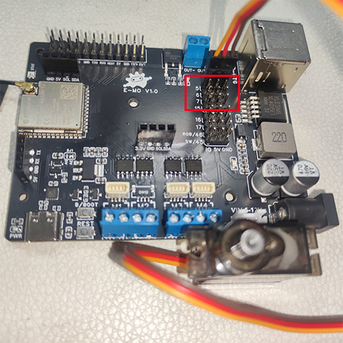
Our example code supports 4 servos, corresponding to the 4 rows of pins marked in the red box in the figure below: 5, 6, 7, and 15;
Each row has 3 columns: the left is the IO pin, the middle pin provides 5V voltage, and the right pin is GND;
Servos are usually controlled via PWM and come with a three-color wire. Insert them onto pins 5 to 15 as shown in the figure. If the servo does not move when running the code, it may be plugged in backward.